Mapping Shapes to Spheres
Please see my first post to read about what I am working towards in this series of posts.
To render a planet or moon, you’re probably going to need to be able to render a sphere. Or maybe an oblate spheroid, but one step at a time, eh?
Rectangles
Many 3D game engines and modelling software suites will come with an easy way
to quickly put a sphere on screen. Here I’ll be using three.js, which has a
SphereGeometry constructor. These tend to work by projecting a rectangle
onto a sphere, much like a typical map of the world, and are known as UV
spheres.
const geometry = new THREE.SphereGeometry(5, 32, 32);
const material = new THREE.MeshBasicMaterial({ wireframe: true });
const sphere = new THREE.Mesh(geometry, material);

scene.add(sphere);
This will result in a wireframe mesh that looks something like this:
This kind of spherical mesh can cause issues when UV mapping a texture onto them, as they have a much higher texel density around the poles. To get around this, texture artists have to stretch the texture at the top and bottom, similarly to how maps of the globe often represent the Arctic and Antarctic regions far larger than they really are. Rectangles just don’t map particularly well to spheres without distortion or stretching, as cartographers well know.
For planetary terrain, we’ll need something that can divide the surface into roughly equally sized segments, regardless of their position.
Icosahedra
One alternative is the icosahedron. By subdividing, or tessellating, the shape
a few times and normalising the vertices to the surface of a sphere, we end up
with a rather convincing sphere. This is sometimes referred to as an
‘icosphere’. In three.js the IcosahedronGeometry constructor can handle
this for us by taking an optional detail parameter.
const geometry = new THREE.IcosahedronGeometry(5, 3);
geometry.computeFlatVertexNormals()
const material = new THREE.MeshLambertMaterial();
const icosphere = new THREE.Mesh(geometry, material);

scene.add(icosphere);
Here I’ve used a Lambert material shader and ensured that the vertex normals are parallel to the face normals for demonstration purposes, as a wireframe didn’t show off the icosphere mesh particularly well at this level of subdivision.
This produces the following mesh:
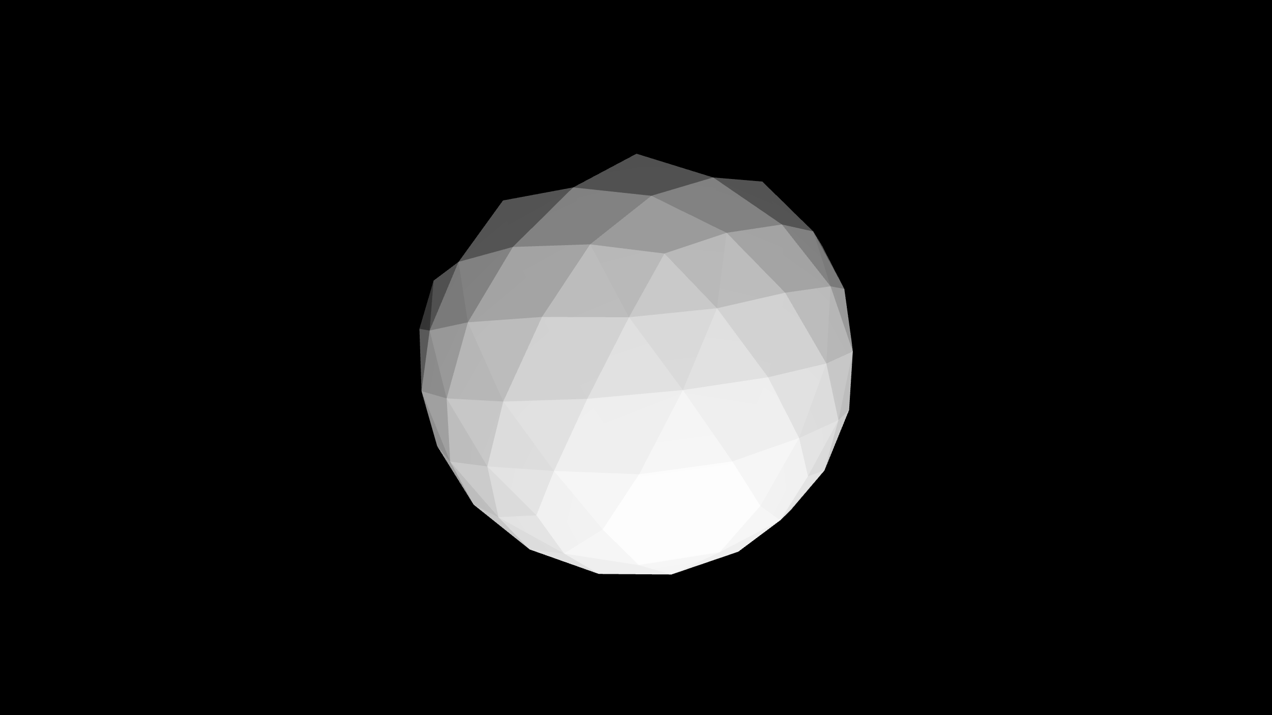
The icosphere is a good fit for our search criteria as it consists entirely of equilateral triangles that are congruent, that is, they are all the same size.
However it is also asymmetric, and while I’m sure it’s possible to adapt a voxel terrain algorithm to a triangular grid, it will likely overcomplicate the implementation of many subsystems.
See here for an example of someone who is building a planetary terrain renderer based upon icospheres.
Other Polyhedra
Instead of an icosphere, another form of geodesic grid could be used.
For example, Goldberg polyhedra are built from hexagons, which might be a good fit for some games. You would, however, need to handle the added complication that there will be exactly 12 pentagons hidden amongst the hexagons.
Cubes
Finally, let’s look at mapping a cube onto a sphere. This can be done in the same way we built an icosphere from an icosahedron. First we tessellate a cube and then we normalise the vertices to the radius of the sphere, so that we are effectively ‘pulling’ them down onto the sphere’s surface.
const geometry = new THREE.CubeGeometry(5, 5, 5, 16, 16, 16);
const material = new THREE.MeshLambertMaterial();

for (const vertex of geometry.vertices) {
    vertex.normalize().multiplyScalar(5);
}

geometry.computeFlatVertexNormals();
scene.add(new THREE.Mesh(geometry, wireframe));
Which results in something like this:
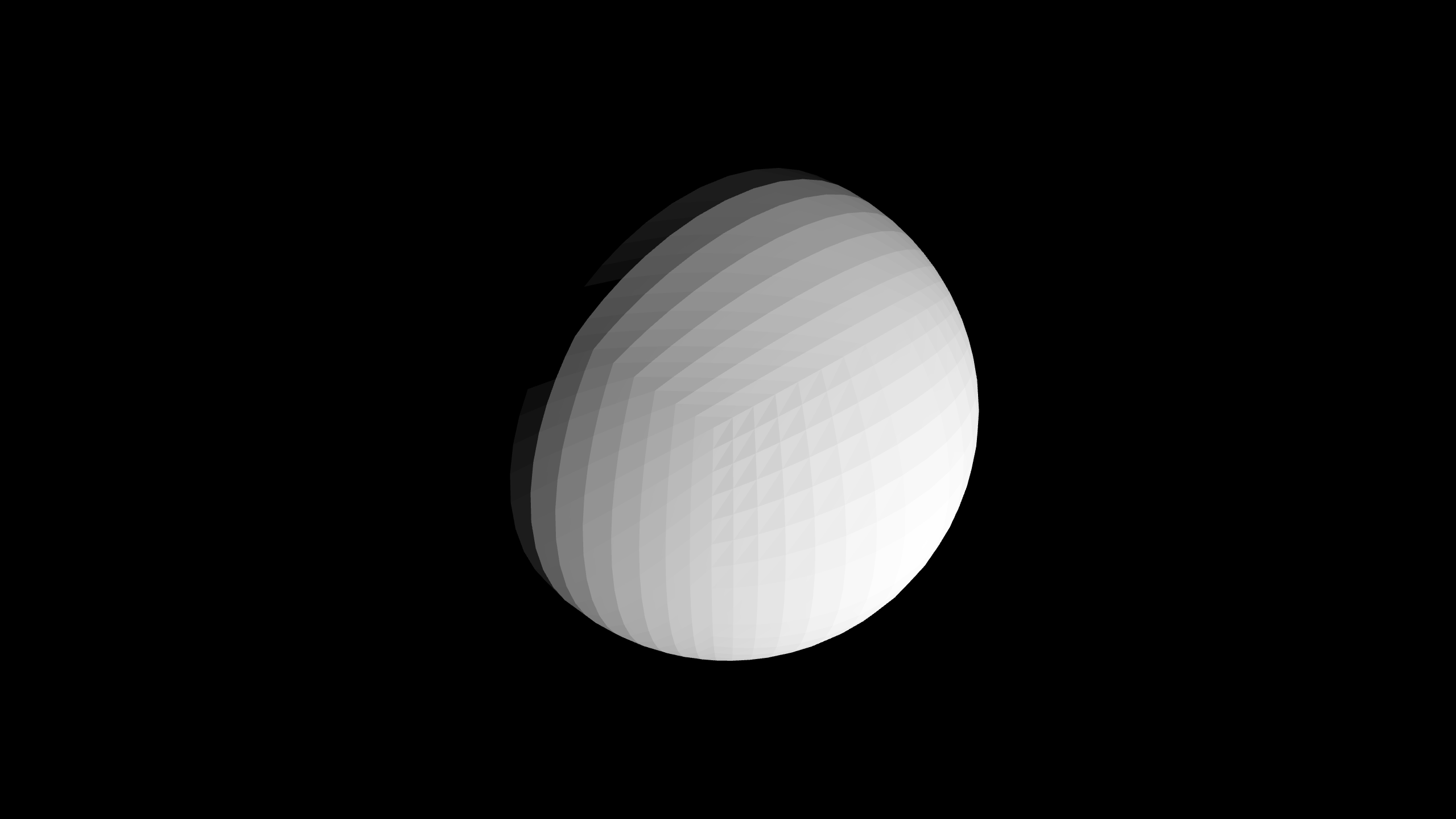
Using a cube is quite a popular technique as it is relatively simple and can produce decent results. There is quite a large amount of distortion occurring at the cube corners in the screenshot above, however this can be mitigated somewhat by increasing the level of subdivision used.
We can reduce the amount of distortion further by improving the mapping algorithm, as described in this tutorial. I won’t go through the maths here, as it is covered in detail in the link. The code should look something like this:
const geometry = new THREE.CubeGeometry(1, 1, 1, 16, 16, 16);
const material = new THREE.MeshLambertMaterial();

for (const vertex of geometry.vertices) {
    vertex.multiplyScalar(2);

    const x2 = vertex.x * vertex.x;
    const y2 = vertex.y * vertex.y;
    const z2 = vertex.z * vertex.z;

    vertex.x *= Math.sqrt(1 - (y2 * 0.5) - (z2 * 0.5) + (y2 * z2) / 3);
    vertex.y *= Math.sqrt(1 - (x2 * 0.5) - (z2 * 0.5) + (x2 * z2) / 3);
    vertex.z *= Math.sqrt(1 - (x2 * 0.5) - (y2 * 0.5) + (x2 * y2) / 3);

    vertex.multiplyScalar(5);
}

geometry.computeFlatVertexNormals();
scene.add(new THREE.Mesh(geometry, wireframe));
The results are shown below:
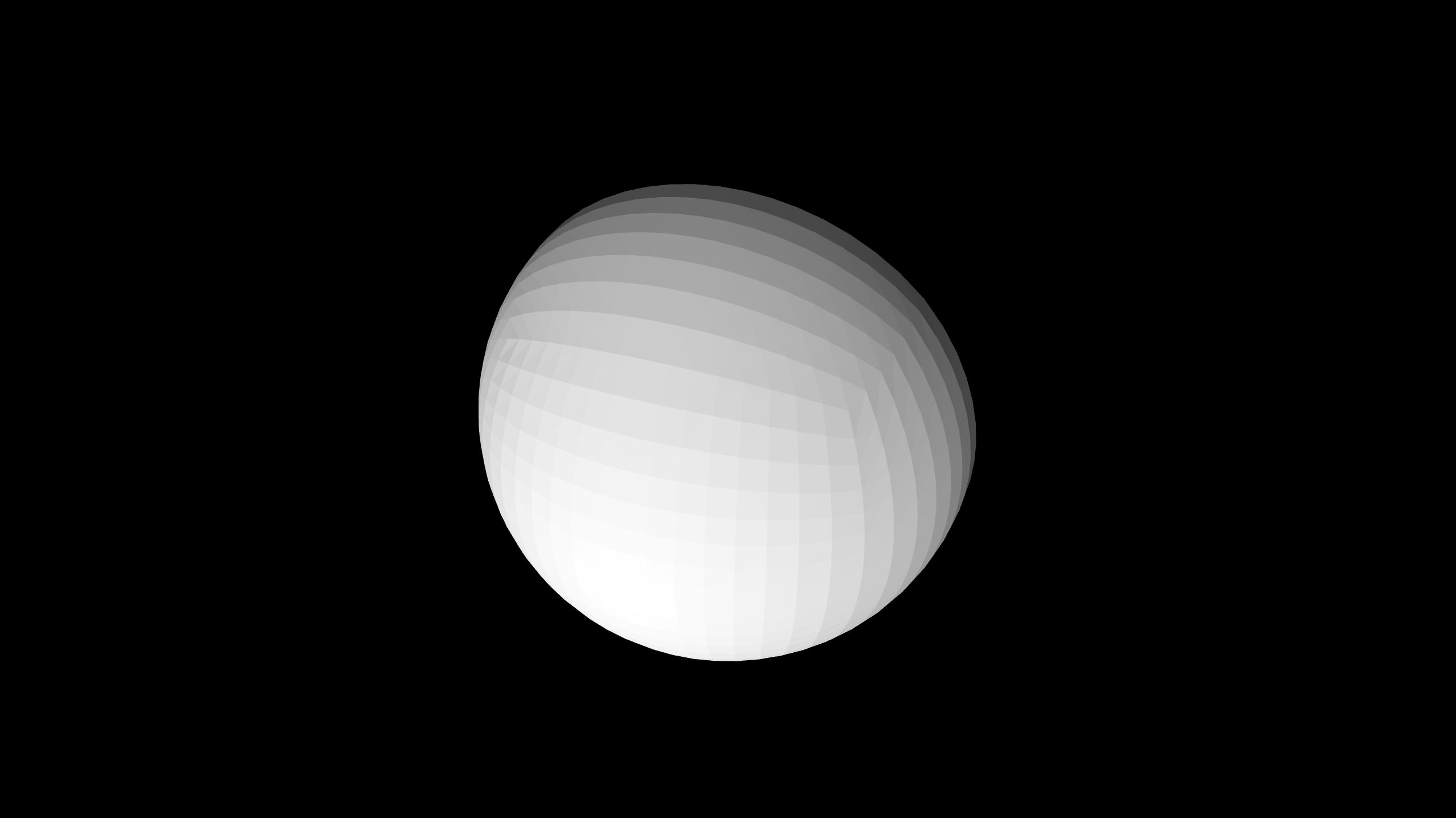
There is still definitely some distortion of the squares at the cube corners, however this algorithm produces squares with more uniform sizes when compared to the normalisation approach.
When combined with a much higher level of subdivision, in practice this should produce results good enough for what we need. A square grid will also be a lot simpler to work with when building systems on top of it.
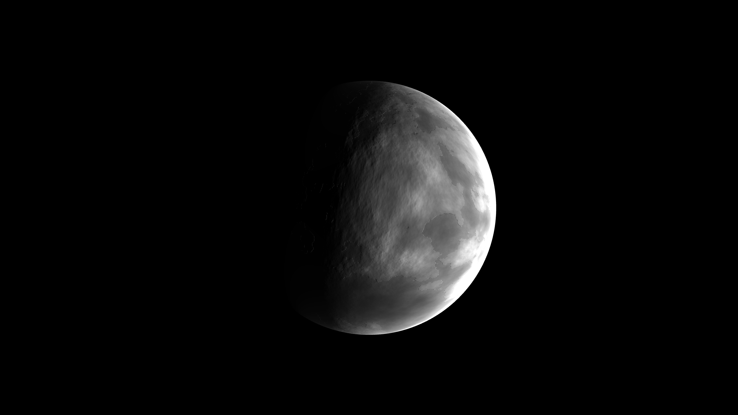
Here’s a procedurally generated moon cube texture applied to this sphere, to whet your appetites!
Conclusion
Today we’ve looked at a few ways to create a spherical mesh and their differences. Moving forward, I will be using the variant of cube mapping that I talked about last, as this strikes a good balance between complexity and quality.
Next time, I will probably dive into level of detail (LOD) techniques, as they are vital to rendering large areas of terrain in real time. So please stay tuned for that!